Esthetic dentistry · Digital workflow

Digital impressions
& veneers

Keep the margin supragingival as long as esthetics allow: once in the sulcus, the retraction cord becomes the safety net.
Smile with ceramic veneers
E.max veneers
Fully digital workflow
02
The rule comes first

The rule: keep the margin high

For veneers, the rule is simple: a supragingival or equigingival margin. Bonding stays on enamel, thin gingiva is preserved, and the restoration remains reversible. Within that framework, the intraoral scanner is not merely sufficient, it is excellent. One clarification from the outset: the numerical values in this article come from studies on posterior crowns, transferred to veneers by reasoning, as the literature offers no quantitative data on anterior teeth.

i
Patient comfort
Up to 75% of patients prefer scanning over conventional impressions: no gag reflex, no unpleasant material.3
ii
Time savings
No more stone models or shipping. STL/PLY files reach the laboratory instantly, enabling richer communication.3
iii
High trueness
On single-tooth preparations, recent scanners achieve a trueness of 20 to 30 µm, matching or exceeding conventional impressions.3
iv
Predictability
Clinically acceptable marginal fit, equivalent to conventional impressions, at least when the margin is optically readable.3
As long as the margin sits at or above the gingiva, the digital versus conventional debate is settled: the scan is more than sufficient. Everything changes the day esthetics force the margin down into the sulcus.
03
The only gateway

When to go below the gum

A subgingival margin is not the standard for veneers, it is an exception. It is justified in only four situations. Outside of them, going deeper brings nothing and puts both the periodontium and the bond at risk. Everything that follows in this article applies only to these cases.

Outside these four cases: the margin stays at or above the gingiva. Going deeper out of habit adds a risk of recession and bonding contamination, with no esthetic benefit whatsoever.3
04
Once you have gone deeper

The blind spot: the cervical margin

The intraoral scanner is a direct line-of-sight optical instrument: it only captures what it can see. As long as the margin remains supragingival or equigingival, all is well. The problem only arises in the cases described above, once the margin has moved below the scallop.

Converging, though limited, data place the tipping point around 0.5 mm below the scallop when scanned without retraction: beyond that depth, the trueness of the file often drifts past 100 µm, and the fit of the finished restoration can exceed the clinical marginal gap threshold of 120 µm. These figures come from studies on molar crowns.16

On an anterior veneer, where the gingiva is thin and the result fully exposed, this inaccuracy is paid for immediately: cervical overcontour, marginal gap, adjustments at bonding, even marginal inflammation. All the more reason to go deeper only when genuinely indicated.

“A veneer never forgives its margin: it shows, it can be felt, it gets inflamed.
Veneer preparation and cervical margin
0.5 mm
Tipping-point depth: beyond it, without retraction, the scan degrades1
>100 µm
Trueness of the file at subgingival depth without retraction, not to be confused with the marginal gap1
120 µm
Clinical threshold for the marginal gap of the finished restoration (McLean & von Fraunhofer)1
05
How failure happens

The three optical obstacles of the sulcus

Understanding why the scanner fails at depth means understanding exactly what the cord is there to correct.

1
Moist sulcus with marginal bleeding
Obstacle 01
Moisture
  • Blood, saliva and crevicular fluid absorb and scatter the structured light
  • A scanner cannot capture a wet surface3
  • Marginal data become noisy or missing
2
Gingiva collapsing over the margin
Obstacle 02
Gingival collapse
  • Without displacement, the gingiva falls back and covers the finish line1
  • The scanner records the gingiva, not the margin
  • Surface registration errors
3
Interproximal shadow zone with tight contact
Obstacle 03
Shadow zones
  • Confocal optics and structured light perform poorly in hidden areas1
  • Narrow interproximal spaces, unfavorable emergence profile
  • Difficulty distinguishing gingiva from the finish line2
Key point: the three obstacles share a common cause: a closed, moist sulcus. The retraction cord acts on all three at once: it opens, it dries, it exposes.
06
The key tool once you go deeper

The retraction cord, the safety net

Once the decision to go subgingival has been made, the retraction cord becomes the key tool. Because the scanner is purely optical, it needs an open, dry field even more than a conventional impression does, since impression material physically penetrates the sulcus. The cord works through three mechanisms: apical displacement of the gingiva, lateral opening of the sulcus, and hemostasis through the impregnated agent (a chemico-mechanical approach). It is not a trivial procedure, however, and the rest of this article details its pitfalls.2
Retraction cord in place
What the cord brings to the scan
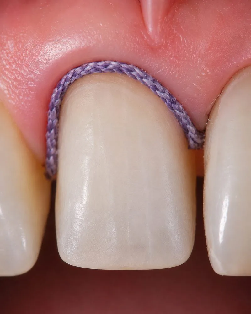
  • Exposed marginThe finish line becomes visible to the optics
  • Dry sulcusThe hemostatic agent eliminates blood and fluid
  • Trueness preservedTrueness kept below 100 µm (82 ± 62 µm), though still scattered1
  • Marginal gap controlledFit brought below 120 µm (95 ± 23 µm at 1 mm)1
  • Stable dataLess noise, fewer registration errors
  • Digital = conventionalWith retraction, the two techniques converge (on molars)2
07
Converging but limited evidence

The data: with or without the cord

The supporting body of evidence comes down to two studies: one in vitro study on a molar and one randomized clinical trial with fifteen patients, also on molars. There are no direct quantitative data on anterior teeth. What follows is converging evidence, not proof.

Without retraction

The margin slips away

  • In vitro molar, 1.0 mm subgingival: marginal gap of 189.1 ± 42.2 µm, beyond the 120 µm threshold1
  • Marginal trueness of 100.1 ± 44.5 µm, a measurement distinct from the marginal gap1
  • Clear degradation from 0.5 mm of depth onwards1
  • Clinically (mandibular molars, n=15), digital scanning without retraction is the least reproducible condition2
With retraction

The margin reads clearly

  • 1.0 mm: marginal gap brought down to 95.2 ± 22.9 µm, below the 120 µm threshold1
  • Trueness at 82.0 ± 61.8 µm: below the threshold but scattered; the clinical benefit of the cord lies mainly in the marginal gap1
  • No more sharp degradation with depth1
  • With retraction, digital is comparable to conventional, especially for shallow margins2
The decisive factor is less the choice between digital and conventional than the management of the soft tissue. An essential reminder: these figures come from molar crowns, not anterior veneers, and they rest on a single in vitro study and one randomized trial with fifteen patients.12
StudyType · nConditionKey result
J Funct Biomater (2025)1 In vitro, maxillary molar, 3D-printed interim crown 0 to 1.0 mm subgingival, ± cord Marginal gap at 1 mm: 189.1 ± 42.2 µm without cord, 95.2 ± 22.9 µm with cord; trueness 100.1 then 82.0 µm
J Adv Prosthodont (2026)2 Crossover RCT, n=15, mandibular molars Digital vs conventional, ± cord Digital without cord the least reproducible; with cord, equivalent to conventional
Sci Rep (2022)6 In vitro · increasing depths Trueness by abutment depth Trueness decreases with subgingival depth
J Clin Med (2025)3 Narrative review · veneers Margin position Recommends equigingival or supragingival margins
Marginal gap (AMD) by depth, in vitro molar, with and without cord, after [1]
Without retraction cord With retraction cord 0 50 100 150 200 µm Clinical threshold: 120 µm 189 µm 147 95 µm 0 0.25 0.50 0.75 1.0 SUBGINGIVAL DEPTH OF THE MARGIN (mm)
Absolute marginal gap on an in vitro maxillary molar [1], at 0.75 mm (147 / 83 µm) and 1.0 mm (189.1 ± 42.2 / 95.2 ± 22.9 µm); the line between data points is interpolated for illustration. Without retraction, the curve crosses the 120 µm threshold between 0.5 and 0.75 mm; with retraction, it stays below. Trueness is a different measurement, to which this threshold does not apply.
08
The procedure, step by step

The protocol that secures the scan

A crucial digital specificity: unlike a conventional impression, the sulcus must remain open during the scan itself. The gingiva rebounds quickly after cord removal: the window is narrow.

1
Prepare
Cervical margin at or just at the gingival scallop. Smooth finish line, rounded angles.
2
Place the cord
Impregnated cord, 7 to 10 min. Single cord for ≤ 0.5 mm. Prefer aluminum chloride over ferric sulfate.
3
Dry
Complete hemostasis, perfectly dry field. The scanner cannot read moisture.
4
Scan
Immediately after cord removal, while the sulcus is still open. Start with the prepared sextant.
5
Verify
Continuous, sharp margin on screen. If drowned in blood: dry again, never force it.
Key move: scan the prepared sextant first, right after cord removal. Every second of delay lets the gingiva close back over the margin.
Double-cord technique (deeper margins): two stacked cords. Just before the scan, only the coronal cord is removed; the apical cord stays in place and keeps displacing the gingiva throughout the acquisition. The step-by-step above describes the single-cord technique, with the cord fully removed.
09
Clinical honesty

Alternatives, caveats & limitations

Advocating for the cord does not mean presenting it as the only solution. Here are the options, their limitations, and the cases where the cord is not the right choice.

Caveat for thin anterior biotypes: on a thin, scalloped periodontium, packing the cord can cause recession. On a veneer, subsequent recession exposes the cervical margin, which amounts to a pure esthetic failure. The cord is therefore not a free move, it is a trade-off. On at-risk biotypes, prefer retraction paste, or give up going subgingival.
Bonding caveat (decisive): a veneer has no mechanical retention; it holds through adhesion alone. Yet hemostatic agents, and ferric sulfate in particular, leave a precipitate that contaminates the enamel and compromises bonding. In an adhesive context, prefer aluminum chloride over ferric sulfate, and clean the surface rigorously before bonding.
The real limitation of this article: most of the figures cited come from crown or in vitro studies. Data specific to thin anterior veneers remain scarce, and systematic reviews still judge them inconclusive.35 The extrapolation is reasonable, but it remains an extrapolation.
10
Three principles to remember

Key takeaways

I
Keep it high
The best subgingival margin is the one you avoid. By default, aim supragingival or equigingival: enamel bonding, preserved gingiva, reversibility.3
II
Go deeper only on indication
Subgingival placement is an exception reserved for four situations (high smile line, masking, cervical lesion, margin already below the scallop), not a routine.3
III
Retract with caution
If you do go deeper, the cord exposes the margin and secures the scan, but it is a trade-off: beware of the thin biotype (recession) and of bonding (aluminum chloride rather than ferric sulfate).12
For veneers, keep the margin at or above the gingiva: that is where digital performs at its very best.
11
Sources

Scientific references

The numerical and clinical claims in this article rely on recent peer-reviewed sources indexed in PubMed. Each citation N in the text refers to this list.

  1. Son YT, et al. Does Intraoral Scanning at the Subgingival Finish Line Affect the Accuracy of Interim Crowns? J Funct Biomater. 2025;16(9):309. DOI 10.3390/jfb16090309 · PMC12470884
  2. Volvaikar PR, et al. Comparison of subgingival finish line reproduction in intraoral scanning versus conventional impressions: a randomized crossover clinical study with/without gingival retraction. J Adv Prosthodont. 2026;18(2):92-102. DOI 10.4047/jap.2026.18.2.92 · PMC13136547
  3. Accuracy of Digital Impressions for Veneer Restorations: A Narrative Review and Case Illustration. J Clin Med. 2025;14(11):3859. DOI 10.3390/jcm14113859 · PMC12156071
  4. Assessment of Healing after Diode Laser Gingivectomy Prior to Prosthetic Procedures. Appl Sci. 2023;13(9):5527. DOI 10.3390/app13095527
  5. Revilla-León M, Gómez-Polo M, Att W, Kois JC. Parameters to Improve the Accuracy of Intraoral Scanners for Fabricating Tooth-Supported Restorations: A Review. J Esthet Restor Dent. 2025. DOI 10.1111/jerd.13364
  6. Trueness of intraoral scanners according to subgingival depth of abutment for fixed prosthesis. Sci Rep. 2022;12:18883. DOI 10.1038/s41598-022-23498-x

Clinical article for educational purposes. Data sourced from PubMed / PMC. The references cited are no substitute for reading the original sources in full, nor for case-by-case clinical judgment. Several data points come from crown or in vitro studies; their extrapolation to anterior veneers should remain cautious.

Hugo Philippe FUSARO

Digital dental design · CAD-CAM workflow · Exocad Trainer

Emailhfusaropro@gmail.com Phone+33 6 15 39 70 53 LinkedInView profile →
Hugo Philippe Fusaro